The System Diagram tab displays CrewCom hardware topology and related CrewNet connections. From this tab, users can add/delete CrewCom devices and manage CrewNet connections.
Note: CrewWare does not allow users to make configuration changes while system is in “Live” mode.
Create or Modify a System Diagram
Create or modify system diagrams during offline sessions by using a drag and drop procedure:
- Select and drag a device from the Device Toolbox pane, then position the device on the grid. (You could perform the same action by clicking Edit > Add in the menu or the Add shortcut button from the top of the screen.)
- Repeat Step 1 to position a second device on the grid, then click and drag the mouse between device ports to draw a simulated connection between devices. The default connection type is copper; change it to fiber when applicable by right-clicking the line and choosing Fiber.
- Repeat Steps 1 and 2 until a complete diagram is constructed.
Tip: To delete a device or connection, right-click on the item and choose Delete, or select the item, click Edit > Delete Device/Connection.

Customizing Your Device Toolbox
Use the “My Toolbox” list in the Navigation Pane to streamline the System Diagram creation/editing process. “My Toolbox” is a customized device list; it is separate from the “Device Toolbox (All)” list.
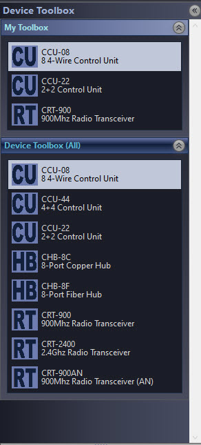
Add a device to “My Toolbox” by right-clicking it and selecting Add to My Toolbox. Remove a device by selecting Remove From My Toolbox. Each list can be collapsed when not in use.
Note: You can also access this feature’s settings from the CrewWare Edit menu.
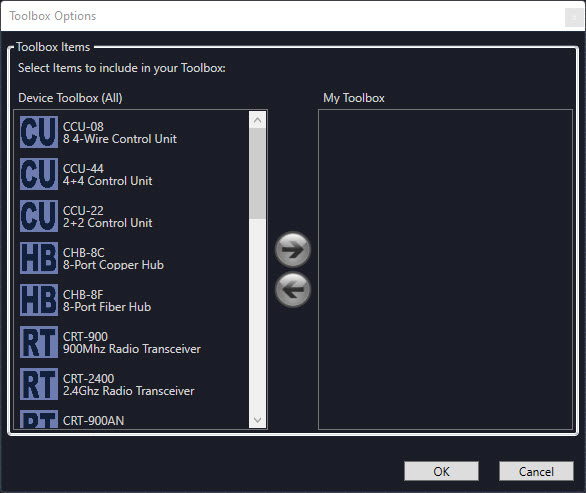
Customize Toolbox Popup Window
System Diagram View Options
The System Diagram tab may be viewed in one of three ways: Diagram View, Port View, or Relay View. Change the view by 1.) choosing an option from the View menu; 2.) choosing a shortcut button in the bottom right corner of the System Diagram panel; or 3.) choosing an option after right-clicking on the diagram.
Diagram View
This view displays all devices currently connected to the CrewCom system.


A High Density RT in a System Diagram
- Green connector lines represent copper connections.
- Purple connector lines represent fiber connections.
- Device icons display the device abbreviation, frequency, mode, device name, and port symbols.
- A dual port symbol on the icon represents a copper/fiber (either/or) CrewNet port. A single port symbol represents a copper-only or fiber-only port.
- Normal Operational Mode Radio Transceivers (RTs) display green circles to represent each of the Radio Packs (RPs) currently logged into that RT. The circles light up when any of the RP’s Talk buttons are engaged (ISO being an exception). Each RT supports a maximum of six RPs.
- Hover the mouse over an individual RP circle to view additional information about that device such as Profile Name, Device ID, Model Number, Operating Mode, etc.
- High Density Operational Mode Radio Transceivers (RTs) display a green bar to visually represent the amount of Radio Packs (RPs) currently logged into that RT and an RP icon at the bottom left to numerically represent the RPs currently logged into that RT. Each RT supports a maximum of 32 RPs. The green squares above the green bar indicate the maximum four simultaneous full-duplex RP talk paths. The green squares light up when any of the RP’s Talk buttons are engaged (ISO being an exception). The square will be red if the active talker(s) has a low battery.
- Hover the mouse over an individual RP square to view additional information about that device such as Profile Name, Device ID, Model Number, Operating Mode, etc.
- An IP-rated RT will show an umbrella icon and IPR inside the icon.
- If desired, print this data by clicking File then Print System Diagram.
Monitor devices from the System Diagram tab during live sessions. If an issue is found, the System Diagram assists in troubleshooting the cause. Double-click an individual device on the diagram to view Device Management information.
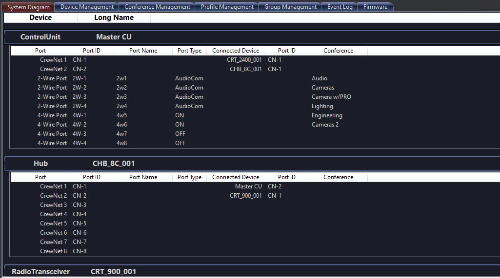
Port View
This view displays the port, port ID, port name, port type, connected device, and Conference information for each device connected to the system. If desired, print this data by clicking File then Print Connection List.
Note: Devices cannot be deleted while working in port view.
In the figure below, you can see that the CU’s CrewNet Port 1 (“CN-1”) is connected to a CRT-2400's port 1. In addition, you can see the Port Type setting and Conference assignments for each of the CU’s 2-wire and 4-wire ports.
Relay View
This view displays the Relay (#1 through #5), Trigger Button Assignment, and Display Name. See Devices Tab - Control Units for more information about customizing these assignments. Users may click on the rectangle R2, R3, R4, or R5 diagram buttons to test the contact closure. (Clicking the Stage R1 diagram does not test its closure.)
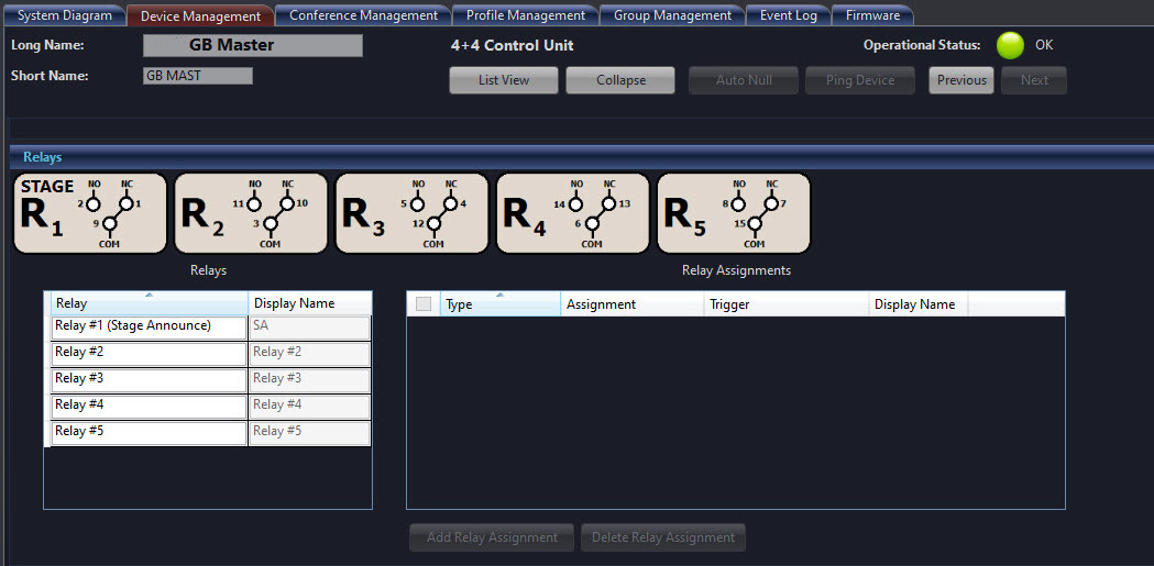
Diagram Preferences
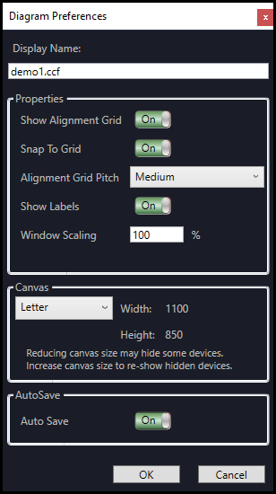
Customize user preferences for the system diagram by opening the Diagram Preferences from the Edit menu. Within this window, you can edit the following:
| Diagram Preferences | |
|---|---|
|
Field/Function |
Description |
|
Display Name |
Displays the active CCF name. |
|
Show Alignment Grid |
Toggles the system diagram display grid on and off. |
|
Snap To Grid |
Toggles the automatic alignment of devices when moved on the system diagram. |
|
Alignment Grid Pitch |
Choose from Fine, Medium or Coarse to set the alignment grid size. |
|
Show Labels |
This function is not currently implemented. |
|
Window Scaling |
Enter a number in this field to adjust the CrewWare interface scale. |
|
Canvas |
Choose a canvas size for the system diagram tab. |
|
AutoSave |
Toggles the auto-save function. When on, the CCF file will automatically save in the following file location every 30 seconds: C:\Users\[username]\AppData\Roaming\Pliant\CrewWare X.X\BKUP |