List View
The Device Management list view of Radio Transceivers displays a summary of each Radio Transceivers's settings.
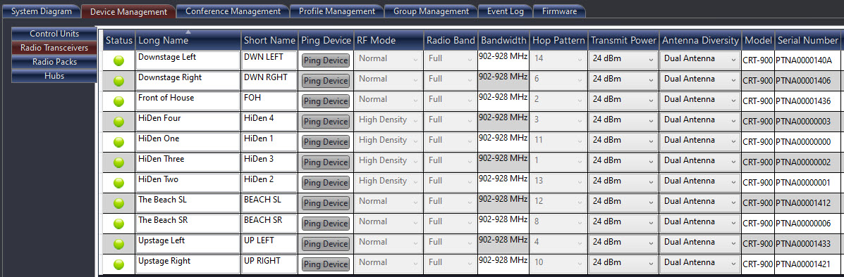
Radio Transceiver List View
Device View
Double-click on a Radio Transceiver in the Device Management list view to access its device view and view/edit its settings. The top section of this view provides an overview of the selected RT, including a list of device information (Serial Number, Model, Firmware Version, and Device ID).
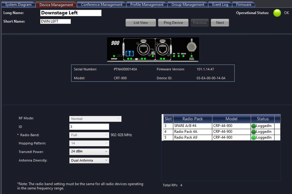
Note: User-defined settings are not saved by device, rather they are saved with the CCF. Therefore, a replacement device receives the same settings as the original device, as long as it is placed in the same location within the configuration.
|
Radio Transceiver - Detail View |
|
|
Field/Function |
Description |
|
Long Name |
Type a name for the selected RT. There is a 16 character limit on the device name. |
|
Operational Status Indicator |
View-only status indication with the following possible statuses: OK (green) and Missing (red). |
|
Short Name |
Type an abbreviated version of the device name to display when needed. There is an 8 character limit on the device short name. |
|
List View Button |
Return to the RT list view. |
|
Ping Device Button |
Device location function where, when activated, both the top ping light and the mode LED on the bottom of the RT will blink until deactivated by the operator. Ping Device Button is also shown after Short Name in List View. |
|
Previous/Next |
Navigate through the device views for each individual Radio Transceiver from the list. |
|
Operational Mode |
Set to Normal by default. High Density is only available for systems upgraded to Version 1.10 or higher. |
|
ID |
View-only field used to identify the RT’s location within the configuration file and system topology. |
|
Radio Band |
Select which segment of the frequency band the RT will operate within. (RF frequency range varies depending on RT frequency.) This setting can only be changed while offline, and may require re-pairing RPs if their radio band is changed.
The Mixed radio band setting allows simultaneous use of both high and low 900MHz bands without limiting the roaming ability of the system's 900MHz RPs. |
|
Hopping Pattern |
Select which Hopping Pattern the RT will operate on. Hopping Patterns must be properly coordinated. CrewCom systems will assist users in assigning compatible hopping patterns as RTs are added to the configuration. It is highly recommended to use these assigned hopping patterns to properly coordinate the system’s RF. This setting can only be changed while offline, and may require re-pairing RPs if their radio band is changed. |
|
Transmit Power |
Selects the RF output power for the selected RT |
|
Antenna Diversity |
Select an option to determine the behavior of the selected RT’s connected antennas: Antenna (R), Antenna (L), Dual Antenna, or Tx:Rx. These options are defined as follows:
|